
Plug-in the microscope to the power supply (1). Switch it on (2) and gradually increase the light intensity up to the desired level (black wheel on the right side of the microscope) (3).

INTERPUPILLARY DISTANCE
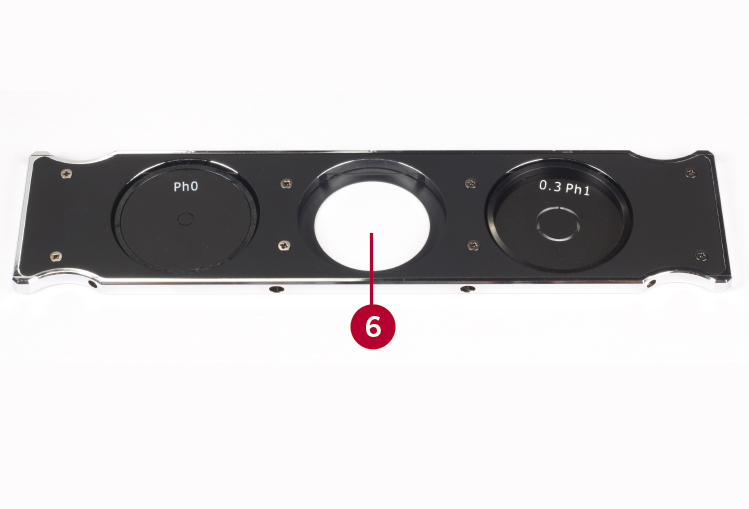
Place a sample onto the stage plate (4), then swing in the 10X objective by manually rotating the nosepiece (5). Push the condenser slider to the middle position (6); in standard configuration this position does not contain an illumination ring for Phase contrast.

Focus the sample by first using the coarse focusing knobs, which are located on the both sides of the microscope (7). Then adjust the interpupillary distance by moving the separate eyepiece tubes in a “butterfly” mode (8). Finally both right and left image should join and become one round image. This setup will allow the user to observe the specimen with both eyes in a relaxed mode.

DIOPTER ADJUSTMENT
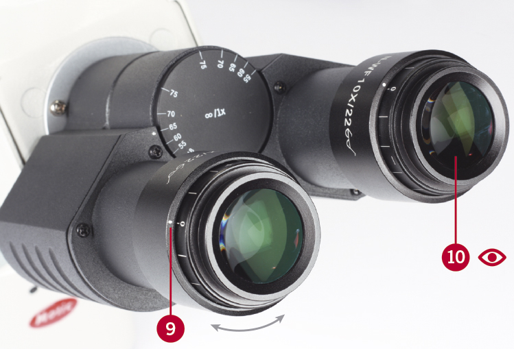
The diopter adjustment compensates any differences in vision between the left and the right eye. First make sure that both eyepieces are in the +/- zero diopter position (9). Look through the right eyepiece with your right eye only (10).

Focus the image precisely by using the fine focus knob/s (11). Then look through the left eyepiece with your left eye only (12). Use now only the diopter adjustment of the left eyepiece to focus the sample. Do not use the coarse/fine focus knob/s for this final adjustment.

Focus the image precisely by using the fine focus knob/s (11). Then look through the left eyepiece with your left eye only (12). Use now only the diopter adjustment of the left eyepiece to focus the sample. Do not use the coarse/fine focus knob/s for this final adjustment.

The microscope is now ready for perfect binocular viewing, according to the user’s eyes, providing an accurate visualisation of the specimen.
BRIGHTFIELD SETUP FOR INVERTED MICROSCOPES AE31E & AE2000
The condenser is an essential component of the microscope, ensuring a homogeneous and high quality illumination for best image results. To setup the condenser properly, please make sure that the 10X objective is in the light path. Place a sample onto the stage plate and focus the sample by the coarse/fine focus (13). Please note that in Inverted microscopes it is the objective (respectively the nosepiece) which is moved in z-direction to find the focus level. Once the image is sharply visible, this focus level is the reference for any further adjustments. Keep this position strictly.


Now close the Field diaphragm (built into the illumination arm) by 1/3 (14). Move the condenser in z-position by using the condenser’s focusing knob on the left side of the condenser carrier (15). Depending on the condenser in use, move it to the LWD or ELWD position markings on the left side of the illumination arm (16). Look through the eyepieces: the illumination spot within the sample image should have a sharply defined border. If not, do a slight correction by moving again the condenser carrier in z-position (17).

*For the AE2000 model, please skip the steps from 14 to 22 and go directly to the Phase Contrast Setup chapter.
On the AE2000, the condenser is supplied centered and these steps are not necessary (Fig.1 on the next page).
Those 2 diagonal screws on the front side of the condenser carrier (18) help to center the light spot, means the illumination in general. Move them until the light spot is placed in the middle of the image (19). Open the Field diaphragm until the complete field is illuminated (20).


Finally we have to use the Aperture diaphragm to adjust image contrast. Use the level on the front side of the condenser body. Move it horizontally until the image shows good contrast and maximum information (21).

The Aperture diaphragm is responsible for the illumination angle, means the Numerical Aperture (NA) of the illumination. For maximum resolution, the NA of the illumination should have the same value as the NA of the objective in use. As with inverted microscopes we use a condenser with a long working distance, such a setup is not possible. Please close the Aperture diaphragm freely until image contrast is satisfying (22). Closing the aperture diaphragm will lower the resolution and brightness but increases the contrast and depth of focus on the sample view. An image with appropriate contrast in most cases can be obtained with an aperture diaphragm closed down to 2/3.


PHASE CONTRAST SETUP FOR INVERTED MICROSCOPES AE31E & AE2000
Phase contrast is a contrast method to visualize samples like smears, cell cultures and other unstained specimen. In Inverted microscopes, mostly petri dishes and well plates are working as a sample carrier. The long working distance of the condenser offers enough space for using a large variety of vessels.
For Phase contrast, especially designed objectives have to be used. Their optical design shows a semi-transparent ring, vacuum-metallized on a specific lens within the objective. This ring corresponds with a suitable annular ring placed in the condenser slider. Once both rings have been aligned to superposition, Phase contrast can work.
All Phase contrast objectives can be recognized by their GREEN labelling (international standard) (23). The code Ph0, Ph1, etc. refers to the physical ring size. All Phase objectives can also be used (with minor restrictions) in Brightfield.


Starting with Phase contrast, first ensure that a correct Brightfield is set up. Keep the proper Brightfield setup when changing to Phase contrast. Open the aperture diaphragm of the condenser completely (24). Choose the objective you like to use and bring the annular illumination ring into the light path by pushing the condenser slider respectively (25).
In AE31E and AE2000 microscopes, Ph1 ring covers the Phase objectives 10X/20X/40X, while PhO as well as the respective objective 4X are optional.
Now remove one eyepiece from the eyepiece tube. This works best if the eyepiece is rotated while pulling it out. Insert the Phase centring telescope (CT) instead (26). Loosen the fixing screw on the centring telescope (27). By pulling out the inner part of the CT, you will focus on the dark ring inside the Phase contrast objective (28).


Attention: This focusing procedure must be done by moving the inner part of the Centering telescope. Please do not touch the coarse/fine focus knobs.
While focusing the dark ring, you also will realize the image of the illumination annulus, which is projected into the same plane (29). If the objective Phase ring (dark) (30) and the illumination annulus (bright) (31) do not overlap, use the two Allen keys supplied with the microscope.

Insert the keys into the countersunk screws at the edge of the phase slider (32). Turn the keys to move the illumination annulus in the slider until the image of the illumination annulus is overlapping with the dark Phase ring (33).


Insert the keys into the countersunk screws at the edge of the phase slider (32). Turn the keys to move the illumination annulus in the slider until the image of the illumination annulus is overlapping with the dark Phase ring (33).

As the Ph1 ring size fits to the objectives 10X/20X/40X, the alignment is done for these objectives. In case of 4X objective lens, the appropriate annulus has to be aligned accordingly using the Ph0 ring. Pull out the Centering telescope (34), push in the eyepiece with a rotating movement (35). If the image of the illumination ring is diverging from the Phase plate in the objective, a low phase contrast image, similar to an oblique illumination, will result.


To insert or replace a Phase ring into the Phase slider, please take care that the Phase ring has got the correct orientation (reading top). Push its edge against the flexible filament until it fits into the hole (36).

If necessary, use the Allen keys to bring the annulus to the centre of the hole (37). The fine adjustment will be done later by the procedure described above; please repeat the steps from point (23) to (35) using the 4X objective lens and the Ph0 ring.


If necessary, use the Allen keys to bring the annulus to the centre of the hole (37). The fine adjustment will be done later by the procedure described above; please repeat the steps from point (23) to (35) using the 4X objective lens and the Ph0 ring.

If you want to know more about our products, visit our Support Zone at
No comments:
Post a Comment